Design and fabrication of
industrial distillation towers !
A step-by-step guide to mechanical design, technical inspection and fabrication
A distillation tower separates the components of a mixture through counter-current contact of liquid and vapour, based on differences in boiling point; from the ADU and VDU in a refinery to aromatics and olefins separation in petrochemicals. Towers can be more than 70 metres tall, and any design or fabrication error is costly.
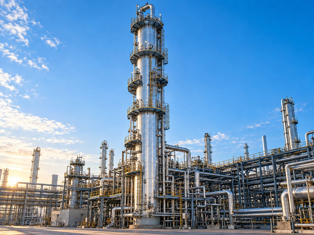
Foreword — design and fabrication of
industrial distillation towers
This article describes the engineering process of distillation towers, from process design in the engineering office, through mechanical design and material selection, to fabrication in the metalworking shop and preparation for shipping to the refinery site.
It is written for design engineers, technical inspectors (QC/QA) and fabrication engineers, and focuses mainly on practical aspects, standards and quality control.
1. Introduction the distillation tower
A distillation column separates the components of a multi-component liquid mixture based on their differences in boiling point. It works by counter-current contact of liquid and vapour: vapour rises from bottom to top and the returning liquid (reflux) flows from top to bottom. At each contact stage, the more volatile components pass into the vapour phase and the heavier ones into the liquid phase, so that the light product collects at the top and the heavy product at the bottom.
In a refinery, the ADU and VDU are the heart of splitting crude oil into cuts. In petrochemicals they are used for polymers, aromatics and olefins. Height can exceed 70 metres; a design or fabrication error can lead to unit shutdown, economic loss and safety hazards, so compliance with international standards is mandatory.
2. Types of tower by internal structure
The choice of internals in the basic design directly affects capacity, pressure drop, efficiency and cost.
Liquid-vapour contact takes place in discrete stages on horizontal plates (trays).
| Tray type | Mechanism | Advantages | Disadvantages |
|---|---|---|---|
| Bubble cap | Vapour enters the liquid layer through the cap | High efficiency, good turndown | High cost and pressure drop, sensitive to fouling |
| Sieve | Vapour passes through holes in the plate | Simple fabrication, low pressure drop, high capacity | Weeping at partial load, narrower range |
| Valve | Movable valve that adjusts with load | Operating flexibility, good turndown | More complex, maintenance of moving parts |
The packing bed creates a continuous contact surface. Random packing (Raschig, Pall ring, Berl saddle): general purpose and lower cost. Structured packing (corrugated sheet): very low pressure drop; suited to vacuum (VDU) and separations with a small boiling point difference.
| Criterion | Tray | Packed |
|---|---|---|
| Pressure drop | Higher | Lower |
| Vacuum operation | Less suitable | Very suitable |
| High liquid capacity | More suitable | More limited |
| Initial cost | Usually lower (large diameter) | Usually higher (structured packing) |
| Liquid distribution | Less sensitive | Needs an accurate distributor |
| Inspection and maintenance | Easier through the manhole | More care in removing/installing packing |
3. Steps of process design
McCabe-Thiele for binary systems (graphical). Fenske-Underwood-Gilliland for multi-component systems: minimum trays at total reflux, minimum reflux ratio, then an estimate of the real trays at the operating ratio.
Actual number = theoretical ÷ overall efficiency (usually Murphree). Efficiency depends on viscosity, surface tension, tray geometry, flow rate and tray spacing.
The ratio of returning liquid to product. Increasing R reduces the number of trays and increases the reboiler/condenser energy cost. The optimum is usually 1.1 to 1.5 times Rmin, from the balance of capital and operating costs.
Aspen Plus and HYSYS, with models such as Peng-Robinson or SRK, give the temperature/pressure profile, reboiler and condenser duties and the internal liquid/vapour rates that form the basis of the mechanical design.
4.3. Shell thickness ASME VIII
The basic thickness formula for a cylindrical shell under internal pressure (Division 1), with the corrosion allowance:
P is the design pressure, R the inside radius, S the material's allowable stress at design temperature, E the joint efficiency based on the type and extent of weld inspection, and CA the corrosion allowance based on the corrosion rate and design life (usually 20 to 30 years). Full RT can raise E to 1.0 and reduce the design thickness.
4. Mechanical and hydraulic design
The diameter must stay clear of flooding and weeping; the height comes from the trays, spacing, skirt and access spaces.
Flooding: vapour velocity prevents the liquid from falling → severe pressure drop and flooding. Weeping: low vapour pressure → liquid leaks through the tray holes. The diameter is usually chosen with Souders-Brown and the Ck factor so that the operating velocity stays at about 70–85% of the flooding velocity.
A function of the actual number of trays, tray spacing (usually 450–600 mm), skirt height, manholes, the bottom sump and the disengagement space at the top of the tower.
Thickness by ASME VIII Div.1 (rules) or Div.2 (analysis/FEA). The H/D ratio can exceed 20; wind load (ASCE 7) and earthquake (UBC / Standard 2800), together with weight and pressure, set the axial and bending stresses and justify a thickness that varies with height. The design of the skirt and anchor bolts is critical.
5. The role of international standards
Div.1: design by rule for most conventional towers. Div.2: design by analysis with lower safety factors and less thickness through FEA; usually economically justified at high pressure or very large diameter.
API 660/661 for the condenser and reboiler. API 620/650 for associated storage tanks. API 12J and API 617/674 for associated separators and pumps. API RP 521 / API 2000 for the pressure relief system and PSVs. These standards also set the framework for inspection, welder qualification, NDT and documentation (such as Form U-1).
6. Material selection (materials)
Carbon steel (SA-516 Gr.70) is economical up to about 400 °C; at higher temperatures Cr-Mo (SA-387 Gr.11/22) is used against creep and hydrogen attack. With H2S or naphthenic acid, stainless cladding (316L or 410S) on carbon steel. At the top of the ADU, at the water + chloride dew point: a more resistant alloy or a corrosion inhibitor. Trays range from carbon steel to 304/316 depending on the severity of corrosion.
| Tower zone | Dominant fluid | Recommended material |
|---|---|---|
| Main shell (moderate temperature) | Hydrocarbon with low corrosion | SA-516 Gr.70 |
| Tower bottom (high temperature + sulphide) | Heavy oil with H2S | Carbon steel + 316L clad |
| Tower top (water and chloride dew point) | Steam + chloride | Carbon steel + inhibitor or resistant alloy |
| Trays and internals | Varies by zone | Carbon steel to stainless 304/316 |
7. Fabrication process in the shop
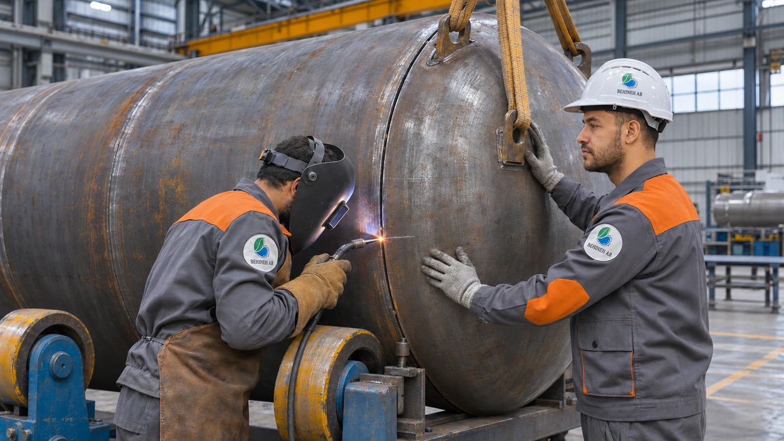
Thick plate (sometimes more than 100 mm) is rolled into a cylinder on a three- or four-roll machine. Clad plate is made by explosion cladding or weld overlay for the resistant layer. Ovality is usually kept below 1% of the nominal diameter.
Longitudinal and circumferential seams usually by SAW. Nozzles by GTAW (root) and SMAW/FCAW (fill). Welders and WPS qualified to ASME Section IX.
Mandatory for alloy steel, thick sections or H2S service (NACE MR0175). Usually about 600–650 °C for carbon steel, with a holding time based on thickness and controlled cooling. The challenge: uniform heating and avoiding distortion.
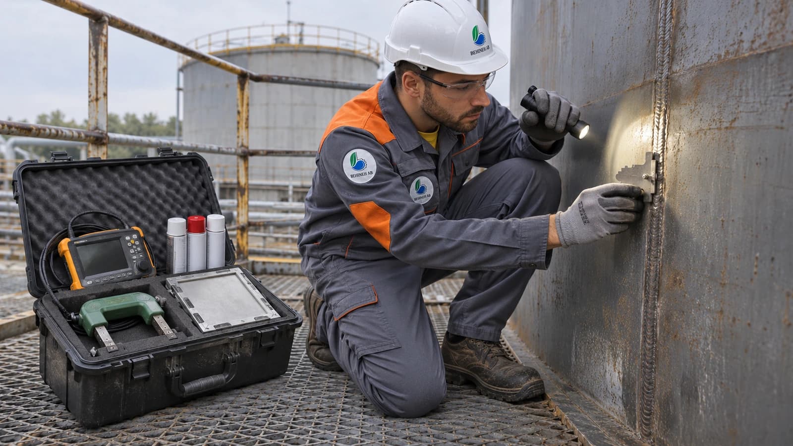
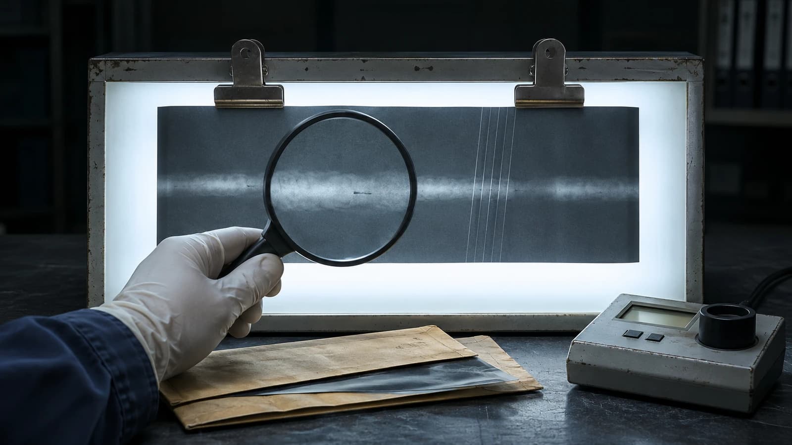
RT for internal defects in the main seams. UT for large thicknesses and measuring remaining thickness. PT/MT for surface defects at nozzles and stress concentrations. Spot versus full RT directly affects E and the thickness.
Deviation from plumb (limited to a fraction of a thousandth of the length) can cause unbalanced loads and disturb the trays. It is controlled with laser alignment and a welding sequence that reduces weld shrinkage distortion.
Trays are installed in sections through the manhole on support rings, precisely levelled. Random packing by controlled dumping; structured packing layer by layer. Liquid distributors to prevent channelling. Demister, feed distributor and packing support grid according to the mechanical drawing.
8. Final tests before shipping
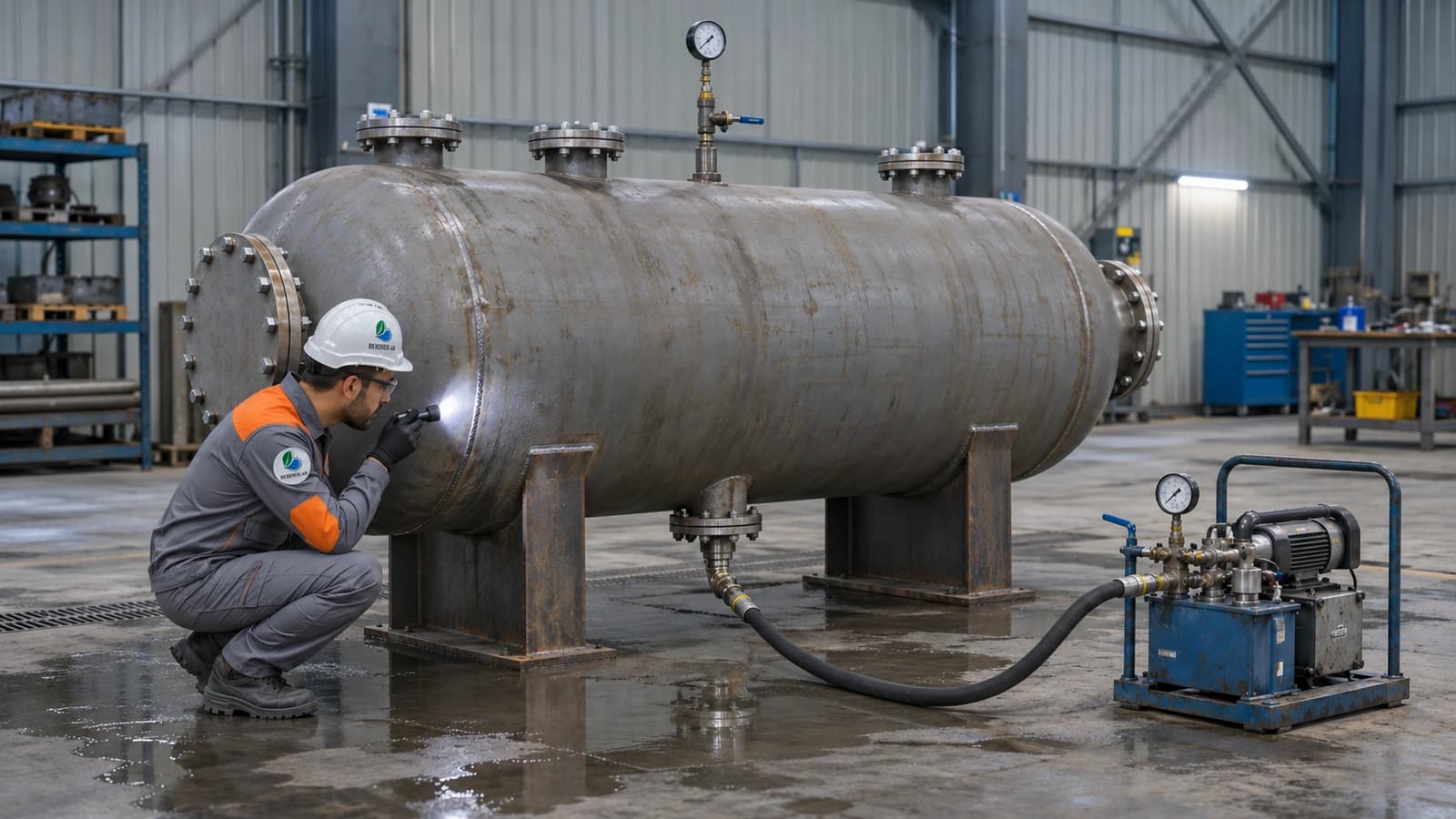
Filling with water and pressurising to about 1.3 times the design pressure (ASME VIII). A vertical test is close to real conditions, but shop space and the volume of water are limiting; for very tall towers it is often done on site. A horizontal test is more common in the shop and needs temporary supports to be calculated; multiple sections receive their final weld on site.
Dimensional checks of diameter, height, nozzles and shell straightness. Additional NDT on repaired welds. Approval of the MDR, MTCs, PWHT and NDT by a third party and the authorised inspector. Protective coating, sealing of nozzles and, if needed, nitrogen purging for transport and storage.
9. Conclusion and new trends
Designing and building a distillation tower is a multidisciplinary process spanning process engineering, mechanics, metallurgy and fabrication. In operation, fouling on trays and packing lowers efficiency and raises pressure drop; choosing suitable internals, a fouling margin and periodic inspection are among the remedies.
New trends focus on cutting energy use: low-pressure-drop structured packing, reflux optimisation through simulation and APC, feed/product heat integration, and the dividing wall column to combine two separations in one structure. Final success comes from accurate calculations, adherence to standards and quality control from the design office to the erection site.
Technical specifications
Trays or packing: which suits your process?
Trays are common for large capacities and a wide operating range. Packing has a lower pressure drop and is better suited to vacuum systems or sensitive separations; however, its sensitivity to fouling and liquid distribution must be checked.
Structural requirements of tall columns
As height increases, wind and seismic loads on the skirt or support become dominant. The shell thickness, stiffening rings and foundation design must be calculated together with the internal pressure requirements.
Applications and industries
Photo gallery
Distillation tower gallery
Frequently asked questions
Request a quote
Distillation tower
Enter the pressure, temperature and fluid; our engineers send a technical proposal and price within 24 working hours.
- Written technical reply with a proposed concept drawing
- Site visit in Tehran and surroundings
- 24-month warranty on fabrication and welding