Design and construction of
industrial hydrochloric acid plants!
Engineering, equipment supply and construction guide for an industrial HCl production and packaging unit
An HCl unit is one of the most complex chemical projects in terms of corrosion and safety; production is by direct H₂/Cl₂ synthesis or by-product recovery, followed by absorption in water for a 30–32% product.
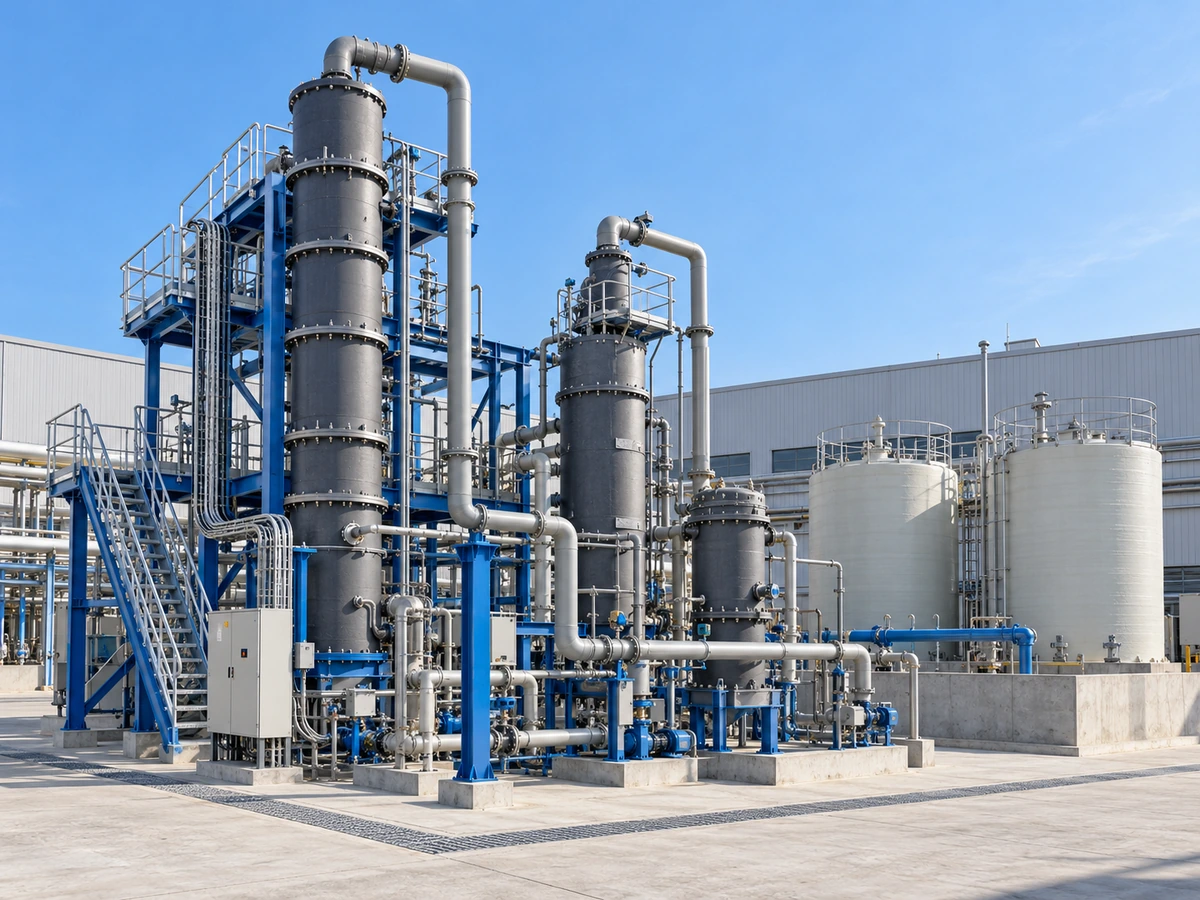
Design and construction of plants
for producing and packaging industrial hydrochloric acid · Behineh Ab Engineering
Hydrochloric acid (HCl) is one of the most widely used mineral acids, from steel pickling (14–18%) to the chemical industry, water treatment, ore leaching and descaling. In terms of corrosion and process safety, building an HCl unit is one of the most complex chemical projects.
Most of the world's commercial HCl is a by-product of processes such as MDI/TDI and PVC. This article covers the path from direct synthesis and absorption to the materials map, automation, HSE, mass-energy balance, the graphite workshop and pre-commissioning.
1. Industrial role and applications
Pickling of hot-rolled sheet. Production of metal chlorides and chemical pH adjustment. Cation resin regeneration and alkaline neutralisation. Ore leaching. High-purity food industry, leather and descaling.
Most of the world's HCl is a by-product of chlor-alkali, phosgenation and hydrocarbon chlorination; this changes the architecture of absorption and pre-treatment.
2. Process methods and technology
The reference for high purity in chlor-alkali units. About 3–8% excess H₂ to eliminate free chlorine. Flame temperature up to 2000–2400 °C with carbon/graphite refractory. Pilot ignition, UV/IR flame detector and a gas shut-off interlock on flame-out.
Gas containing VOCs, moisture and inert gas needs pre-scrubbing. Fluctuations in flow/concentration are managed with a buffer and ratio control. Pre-cooling with a graphite exchanger reduces the tower load.
The common step for a 30–32% product (or up to 37–38%). Thermal management of the tower determines capacity and final concentration.
3. Design of the main equipment
A vertical/horizontal cylinder with a combustion zone and gradual cooling. Refractory layer + insulation + shell with a water jacket. A residence time of a few seconds for conversion >99.5%.
Falling film absorber: resin-impregnated graphite tubes, a film of water/dilute acid, shell side cooling. A secondary packed tower. A tail gas scrubber with water or caustic down to a few ppm.
Graphite block or shell and tube units. Control of the absorption inlet temperature for maximum solubility. In modern designs, heat recovery for low-pressure steam or preheating.
8. Mass and energy balance of absorption
Absorption of HCl in water is strongly exothermic; the falling film dimensions come from the balance and the heat transfer area:
The commercial product is usually 30–32 wt%; close to the azeotrope, 37–38% for special uses. Heat of solution ≈ 60–75 kJ/mol. U for a graphite exchanger is often 300–600 W/m²K. Cooling water at the tower inlet is preferably <40 °C for maximum concentration. Tube liquid loading is usually 0.5–2 kg/(m·s).
4. Material selection and corrosion
CS and most stainless steels suffer pitting, crevice corrosion and sometimes SCC in HCl; the design route is mainly non-metallic or noble metals.
| Material | Strength | Typical use |
|---|---|---|
| Impregnated graphite (phenolic/furan) | Full resistance + high thermal conductivity | Exchangers, falling film, pumps |
| PTFE / PFA lining | Inert up to ≈150–200 °C | Storage tanks, pipes, valves |
| Vinyl ester/phenolic FRP | Economical for large low-pressure volumes | Large tanks, scrubber stack |
| Tantalum | Near-noble resistance at high temperature | Coils and small critical parts |
5. Fabrication and automation
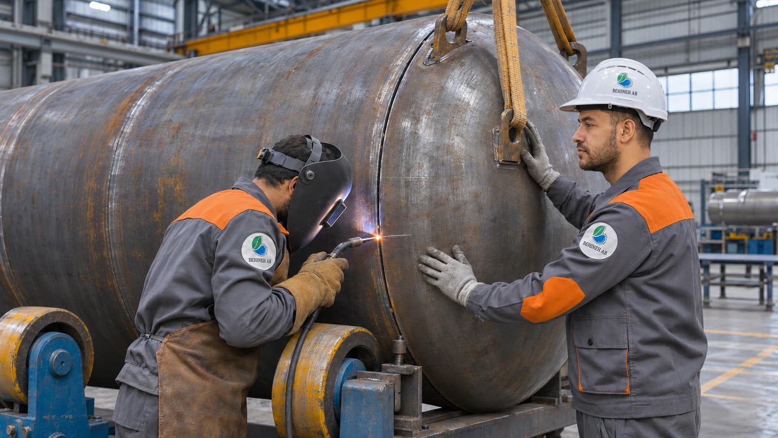
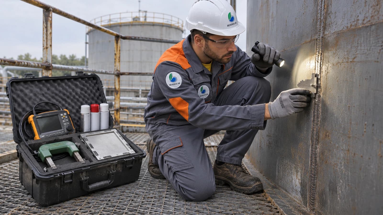
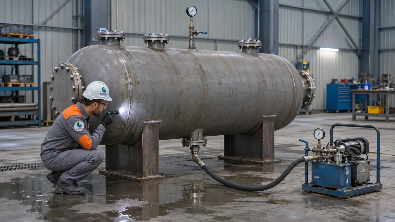
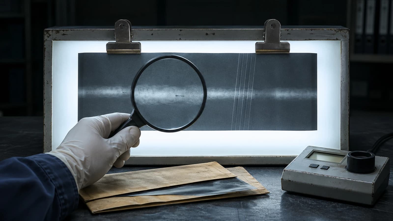
UT and inspection of the blocks, machining without micro-cracks, resin sealing with tie rods at a controlled torque. Hydrotest for metal; for graphite preferably a low-pressure pneumatic test with foaming agent. Weld NDT to ASME VIII. Holiday/spark test for linings.
Online H₂/Cl₂ analyser, ratio controller with a safe H₂ excess, SIS with ESD on ratio deviation or flame-out, temperature/pressure monitoring in the DCS.
6. HSE considerations
A process scrubber + an emergency scrubber with UPS/generator. Ambient gas detectors. Bunds with a resistant coating, showers/eyewash, PPE, a spill procedure with alkaline neutralisation, and periodic drills.
7. New design trends
Heat recovery from synthesis/absorption. Closed-loop cooling water. Predictive DCS and IIoT for graphite health. New-generation composites and coatings with a longer life.
8. Falling film dimensions
M_acid = ṁ_HCl/C, corrected for moisture, with recirculation for a stable film. The number/diameter of tubes from A_HX and standard 50–100 mm tubes. Height from contact time and liquid loading; graphite manufacturer and pilot data take precedence over a pure model.
9. The workshop challenge of graphite
Only a lifting frame on the flange lugs; never chains around the body. Shock cradles and indicators during transport. Foundation level to <2 mm. Flanges tightened in a cross pattern with PTFE/expanded graphite gaskets. The manufacturer's temperature ramp rate. No lateral point loads on the body.
10. Polymer lining
Above 80–90 °C or with an accompanying oxidant → PTFE/PFA. Tanks: Sa 2.5, 3–6 mm sheet with thermal welding, 15–25 kV spark test, loose-fit for expansion. Pipes: factory-lined spools, flared flanges, minimum field joints, supports without stress concentration.
11. Final testing and start-up
≈ 1.5× design without exceeding the manufacturer's ballooning limit. Pressure raised in stages, held 30–60 min, with treated water, then dried with N₂ if needed.
Calibration and SIS testing → purge with N₂ (O₂ <1–2%) → stable hydrogen pilot → gradual introduction of chlorine with excess H₂ → step-by-step capacity increase respecting graphite thermal shock → absorption already on standby → 24–72 hours of steady-state monitoring.
Pressure/leak test reports, calibration of safety instruments, an emergency drill, as-built drawings, the operating manual and personnel training.
Conclusion
The success of an HCl plant lies in combining the process (synthesis or recovery + absorption), non-metallic materials engineering, gas ratio safety, and careful workshop/site execution for graphite and linings.
Behineh Ab Engineering provides design, fabrication of key equipment and start-up support for hydrochloric acid units to suit the concentration, temperature and capacity of the project.
Technical specifications
Why graphite for the exchanger and absorber?
Impregnated graphite combines full chemical resistance to HCl with high thermal conductivity; unlike most non-metals it is ideal for falling film units and exchangers, but it is brittle and needs special handling and installation.
Excess hydrogen at the burner
Usually 3 to 8% excess over stoichiometric is kept so that no free chlorine remains in the product and no yellow colour appears; a ratio deviation is tripped by the SIS.
Lining spark test
After the PTFE sheet is welded, a high-voltage spark test (about 15 to 25 kV depending on thickness) reveals fine pinholes and is mandatory before delivery.
Applications and industries
Photo gallery
Corrosion-resistant equipment gallery
Frequently asked questions
Request a quote
Hydrochloric acid plant design and construction
Enter the pressure, temperature and fluid; our engineers send a technical proposal and price within 24 working hours.
- Written technical reply with a proposed concept drawing
- Site visit in Tehran and surroundings
- 24-month warranty on fabrication and welding