Design and fabrication of
bitumen tanks for industry!
An engineering guide to insulation and shop fabrication of industrial bitumen storage tanks
A bitumen tank combines structure, heat and control; the bitumen must stay at 140 to 180 °C so it can be pumped, without solidifying or oxidising.
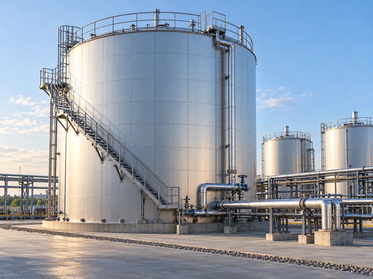
Design and fabrication of
industrial bitumen storage tanks · Behineh Ab Engineering
A bitumen storage tank is a carbon steel vessel that keeps bitumen at a controlled temperature and away from moisture. Unlike tanks for light products, structure, heat and control are integrated here, because bitumen's rheology depends strongly on temperature.
At 140–180 °C (grades such as 60/70 or 85/100 and polymer-modified bitumen) it can be pumped; a drop in temperature means solidifying and pumping stopping, and too much heat means oxidation and loss of penetration. Applications: refineries (blowing unit), export terminals and asphalt plants. This article covers the path from tank types to heating, insulation, fabrication, safety and a shop guide.
2. Tank types by structure
Vertical: several hundred to 10,000+ m³, optimal footprint, ring coils; the vertical temperature gradient needs an agitator or careful coil layout. Horizontal: usually 10–100 m³, elliptical/hemispherical heads, saddles and Zick analysis; a higher surface-to-volume ratio means more heat loss but simpler temperature control.
| Parameter | Fixed (plant) | Mobile / skid |
|---|---|---|
| Typical capacity | 500 to 10,000+ m³ | 10 to 100 m³ |
| Foundation | Concrete, API 650 Annex B | Steel skid |
| Main heating | Central thermal oil | Electric or independent burner |
| Start-up from cold | Several days | A few hours |
| Use | Refinery · terminal | Asphalt · temporary project |
3. Heating systems
The dominant standard for large tanks. The fluid is heated to ≈300 °C in a central heater; seamless 2–4 in coils, serpentine or parallel, on the bottom. Precise control with no direct flame → minimal coking. Needs an expansion tank and an oil network.
Tube surface up to 350–450 °C; controlling heat flux and circulation/agitation is essential to prevent coking. Lower capital cost but poorer control and efficiency — for medium capacities or where thermal oil is not available.
Immersion heaters or trace heating with PID and independent zoning. No fuel on site; electricity cost and infrastructure limit it on very large tanks. Suits small terminals and mobile tanks.
4.1. Shell thickness API 650
For a vertical atmospheric tank, course thickness is calculated by the one-foot or variable-point method:
Allowable stress must be read at the design temperature (not ambient); above ≈150 °C steel strength drops. Annex S has thermo-mechanical requirements above 93 °C. If vapour pressure or transfer with compressed air pressurises the tank, ASME VIII Div 1 governs. Rockwool of 100–150 kg/m³, usually 80–150 mm on the shell and 100–200 mm on the roof; corrugated aluminium cladding 0.6–0.8 mm.
5. Fabrication and assembly in the shop and on site
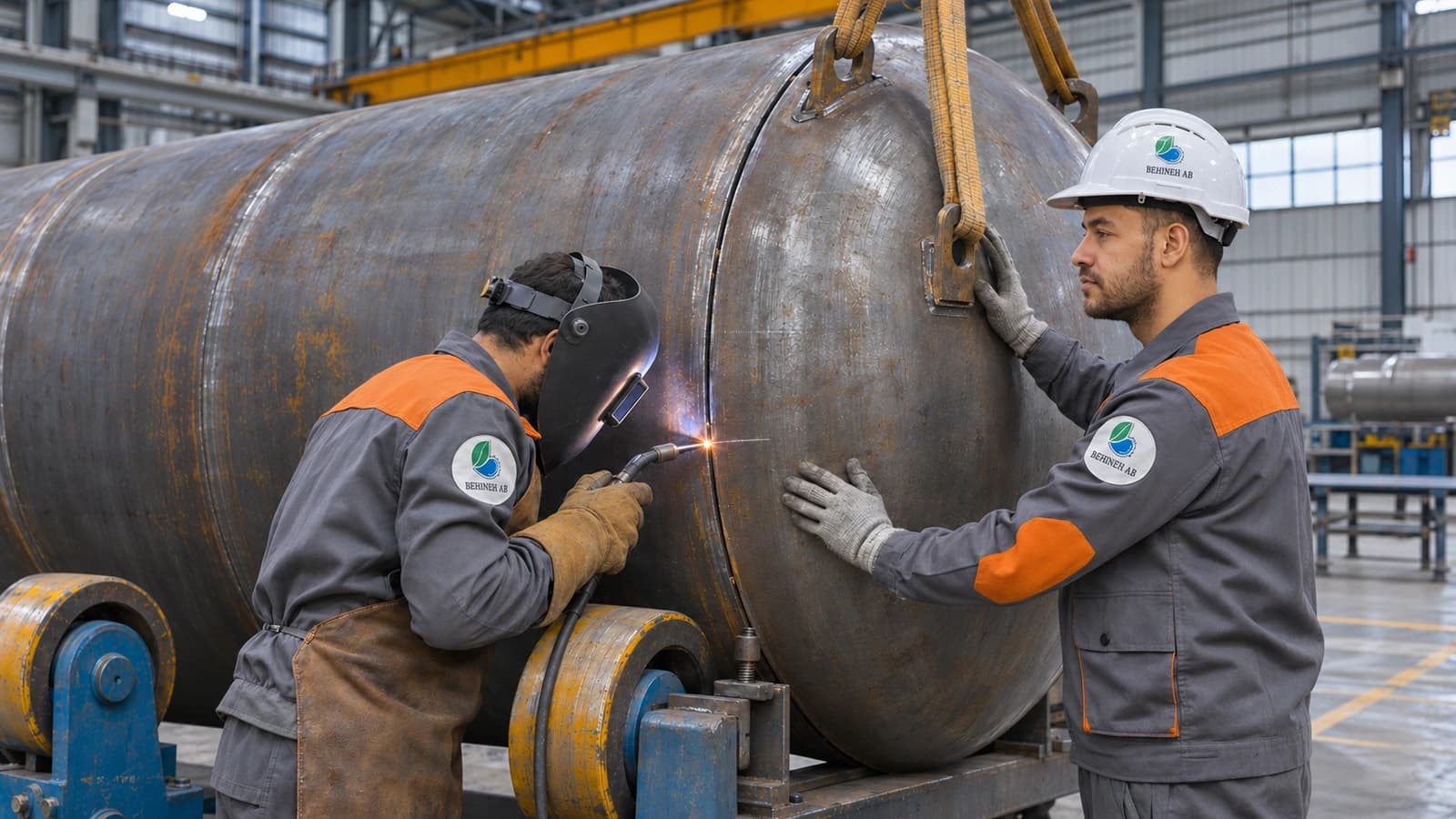
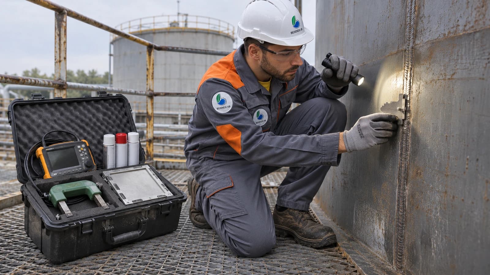
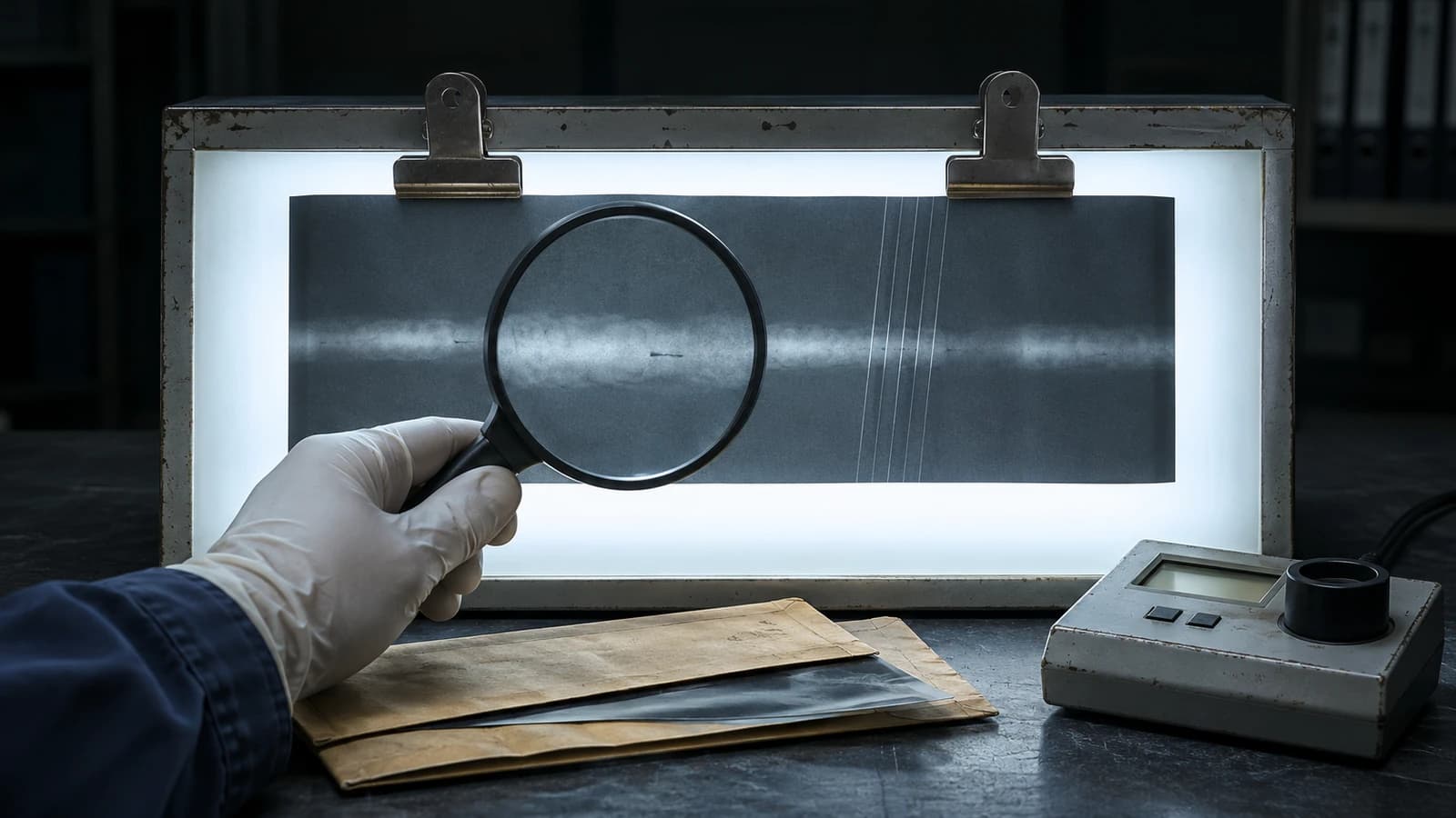
Plate rolling checked with a curvature template. Vertical seams: GTAW/SMAW root + SAW fill; course-by-course erection. WPS/PQR and ASME IX-qualified welders. Spot or full RT, UT of the bottom, MT/PT of fillets, vacuum box on the bottom.
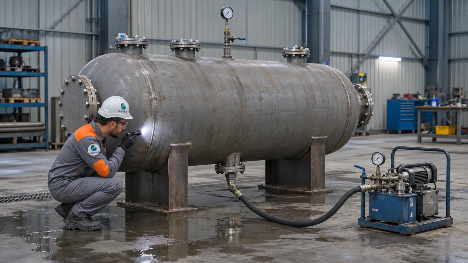
Prefabricated spools on coil supports, held off the bottom. Hydrotest at 1.3–1.5× design for 30–60 min, then a pneumatic test with foaming agent. Full draining and drying of the coil is mandatory — residual moisture risks a steam explosion with hot bitumen.
6. Accessories and safety
Side- or top-entry agitators to prevent settling and even out temperature (especially for polymer bitumen). Multi-level RTDs + PLC/SCADA. Level: guided-wave radar preferred over floats. Emergency drain, P/V valve, foam/sprinkler fire protection, sometimes N₂ blanketing.
Guide: API 650 and shop drawings
Joint efficiency 0.7–1.0 depending on RT level; Charpy at MDMT for cold start-up; Annex S for high temperature; Annex B for foundation and tolerances. Shop package: plate layout, weld details, WPS/PQR, coil layout, ITP with hold/witness points — TPI approval before cutting.
Guide: welding dense coils
Tube spacing is often 150–300 mm. Do as much welding as possible in the open shop; only tie-ins inside the tank. Balanced/backstep sequence and temporary jigs. Coordinate coil installation with the shell courses before the roof goes on.
Guide: insulation and quality control
After hydrotesting the shell/coil and painting (Sa 2.5 + heat-resistant primer). Multi-layer staggered rockwool with bands and pins. Cladding with ≥50 mm overlap in the rain direction; flashing and sealant at nozzles — more than half of insulation loss comes from water entering at exactly these points.
Vacuum box on the bottom; full hydrotest of the shell. Plumbness ≈1/200–1/300 of height, roundness, bottom flatness, nozzle positions. Foundation: level, concrete strength, anchor bolts, drainage slope — before the first course.
7. Results and energy optimisation
The biggest opportunities are sound insulation, watertight cladding, zoning, a heater economiser and predictive control — not just a bigger heater. Delivery with a complete MDR is the basis for later API 653 inspections.
Summary
A successful bitumen tank is the result of an API 650 structure, a suitable heating system, economical insulation and strict quality control of the coil and shop work.
Behineh Ab Engineering designs, builds, tests and delivers fixed and mobile bitumen tanks to suit the capacity and site climate.
Technical specifications
Why is thermal oil preferred over a fire tube?
Central control of the heat-transfer fluid's temperature, with no flame touching the bitumen, reduces the risk of coking and is the industry standard for large refinery tanks.
Why is drying the coil after the hydrotest critical?
Water left in the coil turns to steam on contact with hot oil and causes local pressure or a steam burst in contact with hot bitumen; this step must never be cut short.
Where is insulation weakest?
More than half of long-term performance loss comes from water getting in at nozzles and through poor flashing, not from too little rockwool thickness.
Applications and industries
Photo gallery
Storage tank gallery
Frequently asked questions
Request a quote
Bitumen tank design & fabrication
Enter the pressure, temperature and fluid; our engineers send a technical proposal and price within 24 working hours.
- Written technical reply with a proposed concept drawing
- Site visit in Tehran and surroundings
- 24-month warranty on fabrication and welding